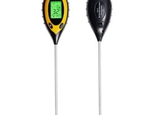
Description
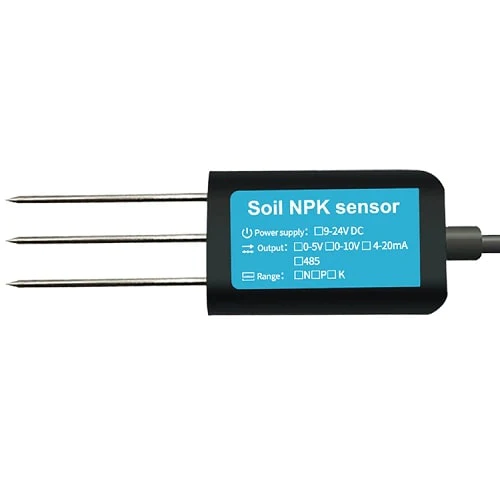
Soil nitrogen, phosphorus and potassium sensor is suitable for detecting the content of nitrogen, phosphorus and potassium in soil. It can judge the fertility degree of soil by detecting the content of nitrogen, phosphorus and potassium in soil, thus facilitating the systematic evaluation of soil conditions by customers.
Features
- Easy to measure, not only for professionals, but also for non-professionals, just insert the instrument into the soil to measure.
- High precision, fast speed measurement, accuracy up to within 2%, and increased stability, more accurate data.
- The resolution is up to 1mg/kg (mg/l), on-site quick inspection, easy to carry, and can be read by inserting into the soil.
- Portable measurement, accurate grasp of the soil fertility status, the user can measure the soil condition at any time, according to the soil condition, the soil fertility can be balanced to achieve a suitable growth environment for the plant.
- The sensor uses high quality chip, low power consumption, high sensitivity and stable signal.
- IP68 grade waterproof and dustproof, to ensure the normal operation of components for a long time. Good sealing performance to prevent moisture from entering the interior of the instrument.
- High quality probe, rust resistance, electrolytic resistance, salt and alkali corrosion resistance, to ensure the long-term operation of the probe part. Therefore, it is suitable for all kinds of soil.
- Suitable for agricultural production, greenhouse breeding, orchard nursery, soil research.
- It is suitable for the detection of alkaline soil, acid soil, substrate soil, seedling bed soil, coconut bran soil.


Getting started with the Soil NPK Sensor
In this tutorial, learn how to interface soil NPK sensor with Arduino board and measure the values of main soil nutrients Nitrogen-N, Phosphorus-P, and Potassium-K present in the soil and display them on OLED Display with I2C support and serial monitor.
Hardware required
- Soil NPK Sensor
- Arduino Nano
- OLED 0.96″ I2C 128X64
- MAX485 TTL To RS485 Module
- Jumper wires
Connecting the Hardware
Connect all the required components as shown in the below schematic diagram to interface Soil NPK sensor with Arduino Nano through MAX485 to display the Soil NPK values on the OLED display.
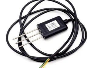
Connect the R0 & DI pin of from the Modbus to D2 & D3 Arduino using Software Serial. Similarly, we have to enable DE & RE high. To do this connect the DE & RE Pins to the D7 & D8 pin of Arduino. The NPK Sensor has 4 wires. The brown one is VCC which needs a 9V-24V Power Supply. The GND pin which is black in color. So connect it to the GND of Arduino. The Blue wire which is the B pin is connected to the B pin of MAX485 & the Yellow Wire which is the A pin is connected to the A pin of MAX485. The 0.96″ SSD1306 OLED Display is an I2C Module. Connect the OLED Display VCC & GND pins to 3.3V & GND of Arduino. Similarly, connect its SDA & SCL pins to the A4 & A5 of Arduino.
Note: RO to pin 8 & DI to pin 9 when using AltSoftSerial

Setting up the library
Install the required libraries listed below before uploading the code:
- Adafruit SSD1306 – Adafruit_SSD1306.h – link
- Adafruit GFX Library – Adafruit_GFX.h – link
- AltSoftSerial Library – AltSoftSerial.h – link
Upload the Code
Errors with Solutions:
Getting 255 for all NPK values:
- RO to pin 8 & DI to pin 9 and RE to D6 when using AltSoftSerial
- Check with connection between sensor and MAX485
- Increase the delay to allow response bytes to be received!
- Maybe you are not using code from the above
Getting no response from sensor data
- Check the baud rate with the sensor manufacturer and try different baud rates
- May be due to sensor or the Modbus module malfunctioning or not working.
Testing the circuit
After successful code upload place the 3 pin steel probe in soil which you want to measure the soil NPK values, and open the serial monitor to see the NPK values, also you can see the NPK values printed on OLED display as the below images.


