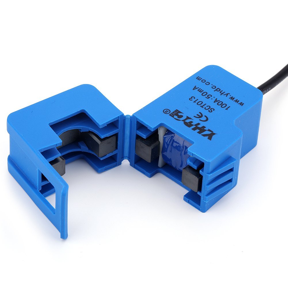
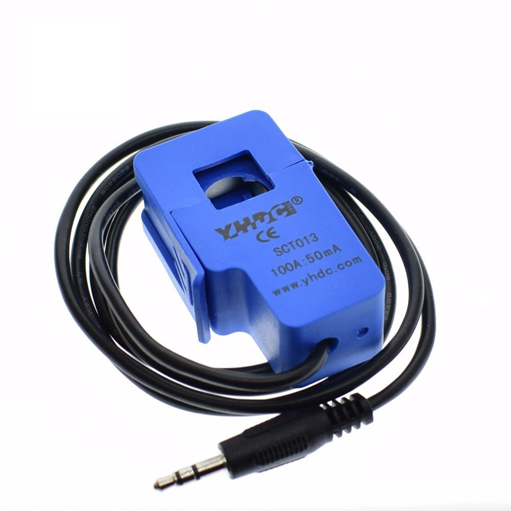
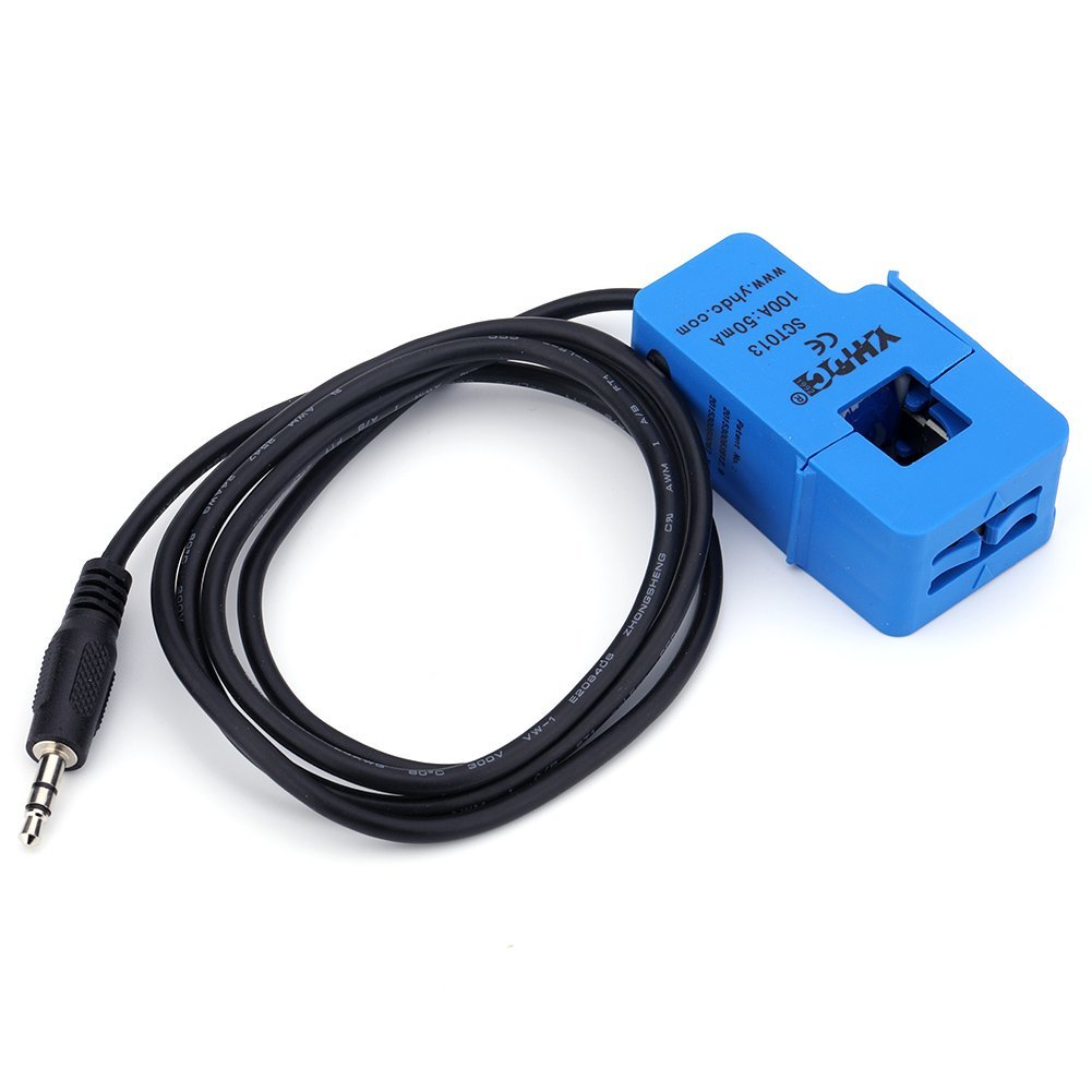
Description
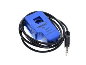
This ac current sensor used for measuring alternating current and it can measure up to 100 A , This split core transformer is particularly suitable for DIY use and it works well with Arduino and Raspberry pi.
Use this split core current sensor to build your own energy monitor, reducing your power usage, or use it build an over-current protection device for an AC load.
Suitable for lighting equipment, AC motors, air compressors, monitoring, current measurement and over-current protection.
- Model: SCT-013-000
- Type: Non-invasive current transformer
- Core Material: Ferrite
- Input Current: 0~100A AC
- Output Mode: 0~50mA
- Leading Wire in Length: 1m
- Cable Jack: 3.5mm (like a headphone jack)
- Turns Ratio: 1: 1800
- Work Voltage: 660 v
- Resistance Grade: Grade B
- Max Sampling Resistance: 10 Ω
- Linearity: ±3%
- Accurancy: ±1%
- Work Frequency: 50-1 KHz
- Work Temperature: -25˚C ~ 70˚C
- Reference project: Open Energy Monitor
- Dielectric Strength: 6000V AC/1min
- Opening Size: 0.51 * 0.51inch / 13 x 13mm
- Two Form of Output: current output or voltage output (a burden resistor needed to add);
- Mechanical strength: opening and closing times, no less than 1000 times (20 ℃)
- High Quality and Safe: Meet the requirement of flame-retardant characteristics (UL94-V0)
Getting started with the SCT013-Non-invasive Clamp AC Current Sensor 100A
This guide details how to build a simple energy monitor on a breadboard that can be used to measure how much electrical energy you use in your home. It measures current, but uses an assumed fixed value for voltage 230V and calculates apparent power. Although not as accurate as a monitor that measures voltage as well as current, it is a method commonly used in commercially available whole house energy monitors for reasons of simplicity and cost.
Hardware required
- Arduino Uno
- 1 x SCT013-Non-invasive Clamp AC Current Sensor 100A
- 1 x Burden resistor 18 Ohms if supply voltage is 3.3V, or 33 Ohms if supply voltage is 5V
- 2 x 10k Ohm resistors (or any equal value resistor pair up to 470k Ohm)
- 1 x 10uF capacitor
- Bread board
- Jumper wires
Connecting the Hardware

Setting up the library
Download the library EmonLib; install the library by extracting that zipped file in the library folder as shown below.

How a CT works
A wire carrying an electric current sets up a magnetic field around it. The wire forms the primary winding of the transformer. The iron (or ferrite) transformer core concentrates the field and couples it to the secondary winding. and, provided the magnetic field continually changes, causes a current to flow in that winding too. That current flows in the burden resistor, which generates a voltage the emonTx can use. A current transformer will not measure direct current.
You can pass more than one wire through the opening of a current transformer if you want the sum (more specifically, the vector sum) of the currents. There are two common instances where this is useful:
- You have a small current and it is difficult to get an accurate reading. In this case, the wire diameter is small. It’s possible to wind it into a coil and the C.T. can be fastened to the coil, or the wire can be passed though the CT opening several times in the same direction, effectively multiplying the current by the number of turns passing through the core. You can correct the reading by changing the calibration of that input.
- You have many small loads on different circuits, and you want to measure the total current used by those circuits. All the circuits must be on the same phase, and all the wires must pass through the CT in the same direction. If one wire passes through the CT in the opposite direction, the current in that wire will be subtracted from the total.
Upload the sample sketch
Open the code directly by the path: File -> Example -EmonLib->current only.

4.Upload the Code, then open the serial monitor. You should the test result.


