Description
Features
- Heart-Rate Monitor and Pulse Oximeter Biosensor in LED Reflective Solution
- Tiny 5.6mm x 3.3mm x 1.55mm 14-Pin Optical Module
- Ultra-Low Power Operation for Mobile Devices
- Fast Data Output Capability
- Robust Motion Artifact Resilience
- -40°C to +85°C Operating Temperature Range
Applications
- Fitness Assistant Devices
- Wearable Devices
Getting started with the MAX30102 PULSE OXIMETER/HEART-RATE SENSOR MODULE I2C INTERFACE
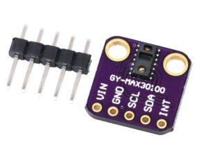
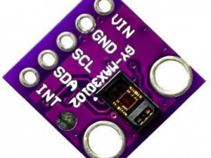
The MAX30102 is an integrated pulse oximetry and heart-rate monitor biosensor module. It includes internal LEDs, photodetectors, optical elements, and low-noise electronics with ambient light rejection. The MAX30102 provides a complete system solution to ease the design-in process for mobile and wearable devices.
Step1: Hardware required
Step2: Connecting the Hardware

Step3: Setting up the library
ESP8266 ESP-12 NodeMCU WeMos D1 Mini WIFI 4M Bytes Development Board Module Library
1. Download and install the Arduino IDE on your operating system (some older versions won’t work).
2. Then, you need to install the ESP8266 add-on for the Arduino IDE. For that, go to File > Preferences.
3. Enter http://arduino.esp8266.com/stable/package_esp8266com_index.json into the “Additional Board Manager URLs” field as shown in the figure below. Then, click the “OK” button.

4. Go to Tools > Board > Boards Manager…

5. Scroll down, select the ESP8266 board menu and install “esp8266 platform”, as shown in the figure below.

MAX30102 Library
you can download it here install the library by extracting that zipped file in the library folder as shown below

Step4: Upload the sample sketch
#include <Wire.h>
#include "MAX30105.h"

#include "heartRate.h"

MAX30105 particleSensor;

const byte RATE_SIZE = 4; //Increase this for more averaging. 4 is good.
byte rates[RATE_SIZE]; //Array of heart rates
byte rateSpot = 0;
long lastBeat = 0; //Time at which the last beat occurred

float beatsPerMinute;
int beatAvg;

void setup()
{
Serial.begin(115200);
Serial.println("Initializing...");

// Initialize sensor
if (!particleSensor.begin(Wire, I2C_SPEED_FAST)) //Use default I2C port, 400kHz speed
{
Serial.println("MAX30105 was not found. Please check wiring/power. ");
while (1);
}
Serial.println("Place your index finger on the sensor with steady pressure.");

particleSensor.setup(); //Configure sensor with default settings
particleSensor.setPulseAmplitudeRed(0x0A); //Turn Red LED to low to indicate sensor is running
particleSensor.setPulseAmplitudeGreen(0); //Turn off Green LED
}

void loop()
{
long irValue = particleSensor.getIR();

if (checkForBeat(irValue) == true)
{
//We sensed a beat!
long delta = millis() - lastBeat;
lastBeat = millis();

beatsPerMinute = 60 / (delta / 1000.0);

if (beatsPerMinute < 255 && beatsPerMinute > 20)
{
rates[rateSpot++] = (byte)beatsPerMinute; //Store this reading in the array
rateSpot %= RATE_SIZE; //Wrap variable

//Take average of readings
beatAvg = 0;
for (byte x = 0 ; x < RATE_SIZE ; x++)
beatAvg += rates[x];
beatAvg /= RATE_SIZE;
}
}

Serial.print("IR=");
Serial.print(irValue);
Serial.print(", BPM=");
Serial.print(beatsPerMinute);
Serial.print(", Avg BPM=");
Serial.print(beatAvg);

if (irValue < 50000)
Serial.print(" No finger?");

Serial.println();
}
Step5: Testing the circuit
Open the serial monitor – this is what I saw, it took a little bit of time for the readings to appear


