Description
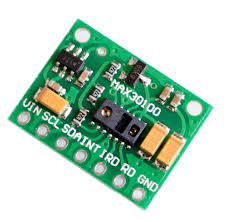
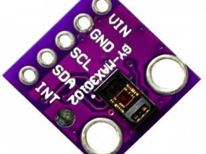
This is a MAX30100 based pulse oximetry and heart-rate monitor sensor breakout board. The MAX30100 sensor combines two LEDs, a photodetector, optimized optics, and low-noise analog signal processing to detect pulse oximetry and heart-rate signals. The MAX30100 operates from 1.8V and 3.3V power sup-plies and can be powered down through software with negligible standby current, permitting the power supply to remain connected at all times.
Specifications
- Interface: I2C
- Dimension: 15.26×15.18×2.55mm
- Weight: 0.8g
- Operating voltage: 3.3v – 5v(Recommended to use 3.3v).
Key Features:
- MAX30100 – SPO2 & Heart Rate Monitoring for real-time health tracking
- Measures Blood Oxygen Levels (SpO2) & Heart Rate (BPM)
- Uses Infrared & Red LED Technology for accurate readings
- I2C Communication Interface – Easy integration with Arduino, ESP32, Raspberry Pi, and other microcontrollers
- Compact & Lightweight – Ideal for Wearables & IoT Health Projects
- Low Power Consumption – Perfect for battery-powered applications
Hardware required
- MAX30100 Pulse Oximeter Heart Rate Sensor Module
- Arduino UNO
- Breadboard
- Jumper wires
Connecting the MAX30100 – SPO2 & Heart Rate Sensor Module to the Arduino
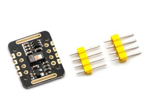
- If you’re facing issues with communication (especially SDA/SCL lines) or power supply consumption , Cut the trace in the place of the red line. This will disconnect all 4.7kΩ pull-up resistors from the 1.8V supply voltage.
- Now make a jumper as shown by the yellow line with a piece of wire or a solder blob. This will pull all the 4.7kΩ resistors up to 3.3V.

Setting up the Arduino IDE
- Download and Install the Arduino IDE
- Go to Tools > Board > Board Manager
- Type Arduino AVR Board and Click Install, Also install ESP8266 board when using nodemcu ESP8266 module in your Arduino IDE.
- If boards are not in the Board Manager, Go to file > Preferences
- Enter http://arduino.esp8266.com/stable/package_esp8266com_index.json (For ESP8266 module), https://github.com/dmadison/ArduinoXInput_AVR.git (For Arduino) , press OK
- Repeat step 3 to install the board.
Installing the Library
- Go to , Tools > Manage Libraries
- Type MAX30100 and Click install the one by Connor Huffine or download it here
See how to install library here

Upload the sample Sketch
#include <Wire.h>
#include “Adafruit_MAX30100.h”
Adafruit_MAX30100 sensor;
void setup() {
Wire.begin();
Serial.begin(115200);
while (!Serial);
if (!sensor.begin()) {
Serial.println(“MAX30100 not found!”);
while (1);
}
Serial.println(“MAX30100 initialized.”);
}
void loop() {
int IR, red;
if (sensor.check()) {
IR = sensor.getIR();
red = sensor.getRed();
Serial.print(“IR: “); Serial.print(IR);
Serial.print(” Red: “); Serial.println(red);
Serial.print(“Mean Diff: “);
Serial.println(meanDiff(IR));
}
delay(10);
}
long meanDiff(int M) {
#define LM_SIZE 15
static int LM[LM_SIZE];
static byte index = 0;
static long sum = 0;
static byte count = 0;
long avg = 0;
sum -= LM[index];
LM[index] = M;
sum += LM[index];
index = (index + 1) % LM_SIZE;
if (count < LM_SIZE) count++;
avg = sum / count;
return avg – M;
}