Description
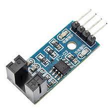
Designed with slotted optical switch sensor, indicator light. Working with official MCU board.Widely used in motor speed detection, pulse counter,
Feature:
- Using imported groove optical coupling sensor, width 5mm.
- It has the output state light, if output high level, the lights are off. if output low level ,it on.
- If it covered,it will output high level;otherwise it output low level.
- Good signal and waveform, with strong driving ability for more than 15mA.
- The working voltage of 3.3V to 5V.
- Output: digital switch output (0 and 1).
- Equipped with a fixed bolt hole, easily install.
- Small board PCB size: 3.2 cm x 1.4 cm.
- Use the LM393 wide voltage comparer.
Specification:
The DO output interface can be directly connected to a micro-controller IO port, if there is a block detection sensor, such as the speed of the motor encoder can detect.
DO modules can be connected to the relay, limit switch, and other functions, it can also with the active buzzer module, compose alarm.
Wiring specification:
- VCC Connect the positive 3.3 5 v power supply
- GND Connect power negative
- DO TTL switch signal output
- AO This module does not work
Application:
Widely used in motor speed detection, pulse count, the position limit, etc.
Getting started with the LM393 Motor Speed Measuring Sensor Module
Here is a motor speed sensor module, the major goal is to check the rate of an electric motor. The module can be used in association with a microcontroller for motor speed detection, pulse count, position limit, etc. In principle, any rate meter simply measures the rate at which some event occurs. Usually this is done by counting the events for a given period of time (integration interval) and then simply dividing the number of events by the time to get the rate.
Hardware required
- LM393 motor speed measuring sensor
- Arduino UNO
- Jumper wires
Connecting the Hardware
the module was connected to an Arduino board and measured the rotation per minute (rpm) rate of a geared robo motor (150rpm@5V) with the help of a home-made encoder disc (resolution 12 slots/disk) attached to its shaft. Final result observed was somewhat close to the spec of the robo motor’s rpm value. Arduino hardware hook up indicator (plus the demo sketch) is given below. Have a try!

Upload the sample sketch
Testing the circuit
open your serial monitor by clicking on the icon in the right top corner(like search icon)


