Description
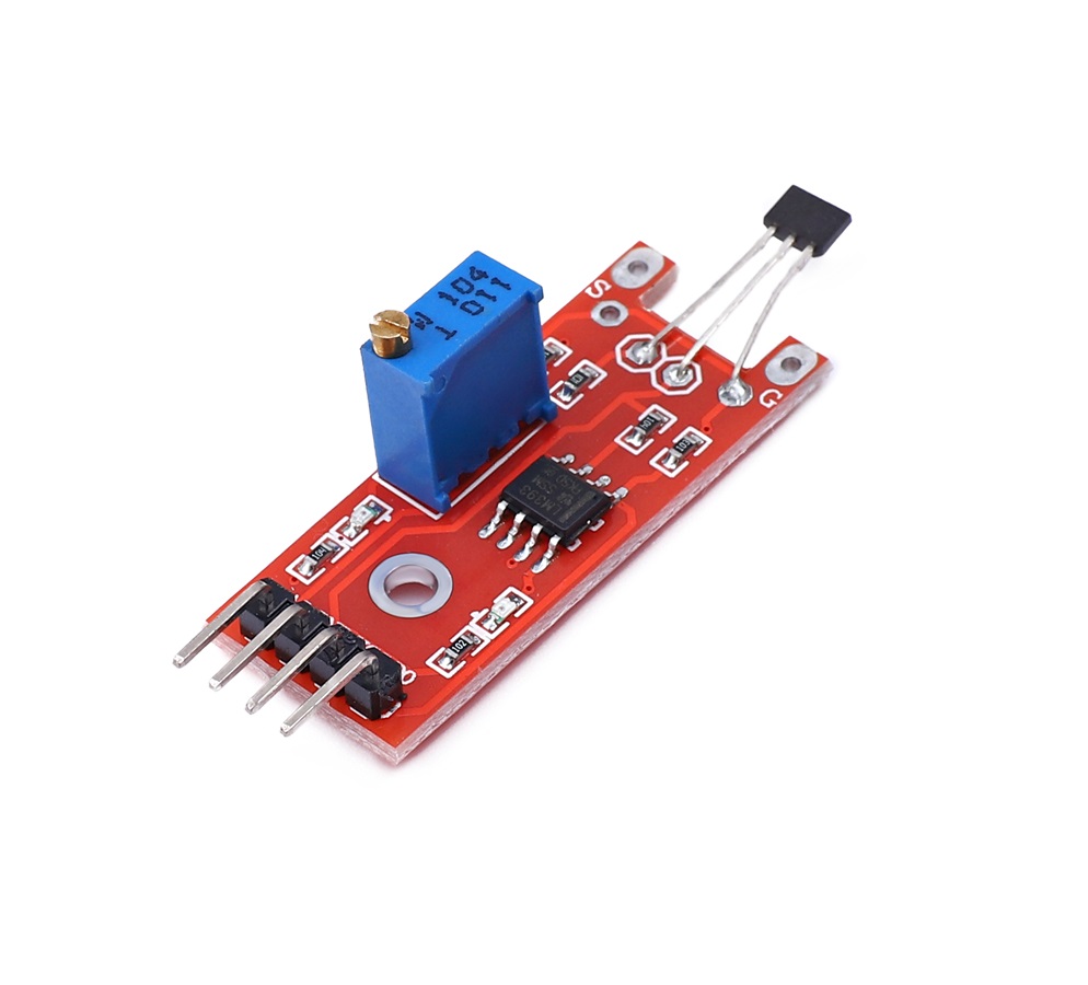
The KY-024 Linear magnetic Hall sensor reacts in the presence of a magnetic field. It has a potentiometer to adjust the sensitivity of the sensor and it provides both analog and digital outputs.
The digital output acts as a switch that will turn on/off when a magnet is near, similar to the KY-003. On the other hand, the analog output can measure the polarity and relative strength of the magnetic field.
The KY-024 module consists of a 49E Linear Hall-Effect Sensor, a LM393 Dual Differential Comparator, a potentiometer, two leds and six resistors. It’s compatible with popular electronics platforms like Arduino, Raspberry Pi, Esp8266 and Teensy.
Specification
High sensitivity IR receiver
Extremely sensitive to wave between 760-1100nm
Power supply indicator lamp
Comparator output indicator lamp
Analog quantity output
Threshold rollover electric level output
Threshold adjusted by potentiometer
AO, real-time thermistor voltage signal output
DO, high / low electric level signal output
Detection Angle Range: About 60 degrees
Power Supply: 2.7-6.5 V DC
Hole Inner Diameter: Approx. 3mm
Size (L x W): Approx. 36 x 16mm
Getting started with the KY-024 Linear Magnetic Hall Sensor
A hall effect sensor is a sensor that varies its output based on the presence or absence of a magnetic field. This means that the output signal produced by a Hall effect sensor is a function of magnetic field density around it. When the magnetic flux density around it exceeds a certain pre-set threshold value, the sensor detects it and generates an output voltage sometimes called the hall voltage to indicate the presence of the magnetic field.
Hall sensors produce either analog or digital output depending on the particular sensor. Whichever type, they usually come in a three pin package with one pin to represent signal and the other two to provide power to the sensor. This makes easy the connection to any microcontroller.
For today’s tutorial, we will demonstrate how the hall effect sensor works by connecting it alongside a LED to an Arduino. The Arduino will be programmed such that when a magnet is brought close to the hall effect sensor, the LED comes on and when the magnet is removed, it goes off.
Hardware required
- Arduino Uno
- KY-024 Linear Magnetic Hall Sensor
- Jumper wires
Connecting the Hardware
The schematic for this project is a simple one, as all we have to do is connect the three pins of the hall sensor and an LED to the Arduino. Connect the components as shown in the schematics below.

Hall Sensor – Arduino
The LED can be plugged directly into the Arduino with the positive leg in Arduino pin 13 and the other leg plugged into the ground pin without a resistor because Arduino has an internal resistor attached to pin 13.
Upload the Code
The code for this project is really simple, all we want to do as earlier mentioned is to check if a magnetic field is being sensed and if yes, turn on the LED if no, we turn off the LED.
int hallSensorPin = 2;
int ledPin = 13;
int state = 0;
void setup() {
pinMode(ledPin, OUTPUT);
pinMode(hallSensorPin, INPUT);
}
void loop(){
state = digitalRead(hallSensorPin);
if (state == HIGH) {
digitalWrite(ledPin, HIGH);
}
else {
digitalWrite(ledPin, LOW);
}
}
Results
Copy the code and upload to your Arduino board. You should see the LED switch when a magnet is brought close to it .


