Description
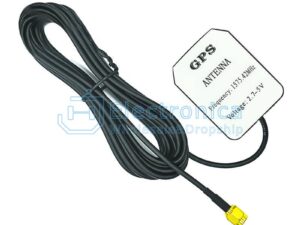
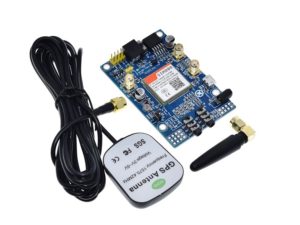
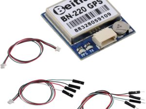
NEO-6M GPS module with antenna and build-in EEPROM
This module is compatible with APM2 and APM2.5, and EEPROM can save all your configuration data.
Interface: RS232 TTL
Power: 3-5v
Baudrate: 9600 by default
How to get started with GPS Receiver NEO-6MV2
The NEO-6 module series is a family of stand-alone GPS receivers featuring the high performance 6 positioning engine. The 50-channel 6 positioning engine boasts a Time-To-First-Fix (TTFF) of under 1 second. The dedicated acquisition engine, with 2 million correlators, is capable of massive parallel time/frequency space searches, enabling it to find satellites instantly. Innovative design and technology suppresses jamming sources and mitigates multi-path effects, giving NEO-6 GPS receivers excellent navigation performance even in themost challenging environments. All NEO-6 modules are based on GPS chips qualified according to AEC-Q100’ industry proven PPP algorithm provides extremely high levels of position accuracy in static and slow moving applications, and makes the NEO-6P an ideal solution for a variety of high precision applications such as surveying, mapping, marine, agriculture or leisure activities. The SPI interface allows for the connection of external devices with a serial interface.
Overview
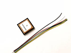
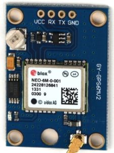 The module has 4 pins :
- VCC: Power supply
- GND: Ground
- RX: Receiver
- TX: Transmit
The module is incredibly simple: it just spits non stop NMEA data strings to the TX pin. NMEA” stands for “National Marine Electronics Association” and is a standard text protocol shared by all GPS.
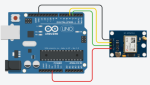
Connecting the GPS Module to Arduino
To connect your GPS module to Arduino, use a +5V from the power side of the Arduino and any ground pin. Any two pins will work for the serial communication, but on this tutorial we will use 3 and 4:
- Connect Arduino pin 3 to the RX pin of the GPS Module.
- Connect Arduino pin 4 to the TX pin of the GPS Module.
Installing a library: TinyGPSplus
Open your Arduino IDE and go to Sketch>>Include Libraries>>Manage Libraries.
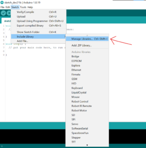
Search for TinyGPSplus and install the Library.

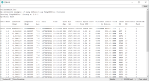
After installing the library, upload this codes into your board. It’s FullExample edited sketch.
Here we used 115200 baud rate and RX and TX of GPS are connected to 3 and 4 respectively. To know that your GPS has got connected, its LED will blink continuously. If not yet blinking, wait a moment.
Open your Serial Monitor, set your baud rate(115200) and you should get the coordinates.