Description
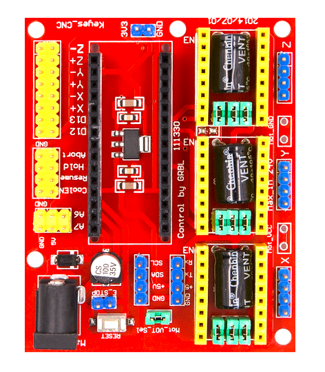
This a CNC shield V4 that properly work with Arduino Nano board. It can be used as driver expansion board for engraving machines and 3D printers. It has in total 3 channel slots for A4988 or DRV8825 stepper motor driver modules for driving 3 channel of stepper motors. Each channel of stepper motor only needs 2 IO ports, which means 6 IO ports is sufficient to manage 3 stepper motors. This shield can make quick work for managing stepper motors in your project.
Features:
1. 3 Axis stepper motor driver
2. Compatible with micro-drive laser engraving machine, three-axis CNC engraving machine,.
3. 2A can be controlled within the two-phase four-wire stepper motor.
4. Released the digital IO interface, easy to connect to other modules, such as ENDSTOP.
5. Released the I2C interface, you can connect to the LCD I2C or other I2C module.
6. Power DC5V interface, 7.5-12V voltage input.
7. GRBL compatible
8. Worked with nano.
Interfacing CNC Shield V4 Engraving Machine Expansion Board for Arduino Nano
1. With arduino directly.
this methode we used here allows you test if your CNC Shield V4 Engraving Machine Expansion Board for Arduino Nano is working fine. to achieve on successful testing operation follow this steps:
- Insert the stepper motors drivers (A4988 or DVR8825) and Arduino nano in their slots respectively as show in picture below:

2. Connect the arduino nano to computer via a nano USB >>open arduino IDE>>copy and paste the codes below in your IDE then compile it and upload it to arduino.
3. After downloading the codes to the arduino nano connect the stepper motors to their port
i.e X,Y,Z respectively as shown in picture below:

4. While arduino nano disconnected to the computer USB you can then connect the CNC shield via a dc jacket to 12Vdc and seing the stepper motors stepping according to the instruction in laterly uploaded codes.
2. With GRBL.
1) Install the grblmaster library file and burn program
This will allow you to get the filmwares that will be being excuted while you are Serially controlling your stepper motors. Download and install to your arduino IDE a grblmaster.zip
After that the grblmaster folder will be self placed to libraries in Arduino IDE installation directory.
Open Arduino IDE, choose File->Examples->grbl->grblUpload, Open it , select the port and board type, burn this grbl sample program to Arduino NANO.
2) Install Grbl Controller
Download and install Grbl Controller,open it, interface as shown in picture:


Use the USB cable to connect your PC and Arduino NANO then supply your CNC sheild with 12Vdc, select the port and select the baud rate as 9600. Click “Open”, if it connected, “Open” will be “Close/Reset “, the background is red. Click “Choose File” to choose the graphy you want to engrave, after selected click “Begin” to engrave.
NOTE:
while using this CNC shield V4 especially for those made in china you met with a problem cause Whoever made this shield made a mistake and put the pins that should go to Vcc, to GND. to use it you may modify it a bit by cutting a wrong connections and relink the connections again in proper way by soldering VCC to VCC and GND to GND as indicated below:
- Start by cutting wrong connections

2. After you are done by cutting wrong connections and verify relink/resolder the shield as shown below:
GND to GND
Vcc to Vcc

and here you are done with your cnc shield connections corrections.


