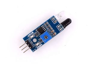
Description
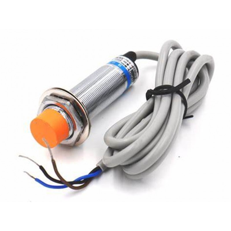
Capacitance proximity sensors are used for non-contact detection of metallic objects. Their operating principle is based on a coil and oscillator that creates an electromagnetic field in the close surroundings of the sensing surface. The presence of a metallic object (actuator) in the operating area causes a dampening of the oscillation amplitude. The rise or fall of such oscillation is identified by a threshold circuit that changes the output of the sensor. The operating distance of the sensor depends on the actuator’s shape and size and is strictly linked to the nature of the material:
| Sensitivity when different metals are present. Sn = operating distance. | |
| Fe37 (Iron) | 1 x Sn |
| Stainless steel | 0.9 x Sn |
| Brass – Bronze | 0.5 x Sn |
| Aluminum | 0.4 x Sn |
| Copper | 0.4 x Sn |
As it is capacitive type proximity switch, its detecting object target is not limited to only conductor, but also liquid and even powder things, like plastic, water, glass, oil, etc.
Features
Specification:
- Working Voltage: DC 6V – 36V
- Loaded Current: 300mA
- Response Frequency: 500Hz
- Detect Range: 0 – 4mm
- Switch Appearance Type: Cylinder Type
- Theory: Induction Sensor
- Output Pin: NPN 3-wires Normally Open
- Working Environment Temperature: -25°C ~ + 70°C
- Wire Length: 1.2meter
- Protection degree: IP 65
- Body Material: Alloy & Plastic
- Sensor: Iron 10.5 x 10.5 x 1mm
- Dimensions : 2.2 x 6cm
- Net Weight: 85g
Pin-outs:
- Brown – VCC (+)
- Blue – Ground (-)
- Black – Trigger Signal
Getting started with the Capacitance Proximity Sensor switch NPN NO DC 6-36V 300mA 1-10mm
when you take metal near to the sensor it induces more current which results in higher voltage. In this example you need to open your serial monitor to see the incoming signal from the analog pin then make a threshold to determine if metal is detected or not.
Hardware required
- Arduino UNO
- Capacitance proximity sensor
- Jumper wires
Connecting the Hardware
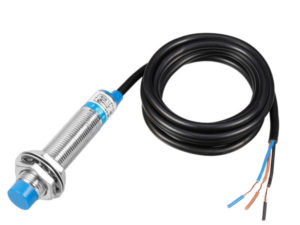
The metal proximity sensor will have three color wire. The blue should be in the ground,Black – Trigger Signal is on analog pin A0,brown is on +VCC which should be giving to Arduino + 5v VCC

Arduino Sketch
float metal;
int reading;
int metalPin = A0;
void setup()
{
Serial.begin(9600);
}
void loop()
{
reading = analogRead(metalPin);
metal = (float)reading*100/1024.0;
Serial.print(“Metal in Proximity = “);
Serial.print(metal);
Serial.println(” %”);
if(reading>250)
Serial.println(“Metal Detected”);
delay(1000);
}
Testing the circuit


