Description
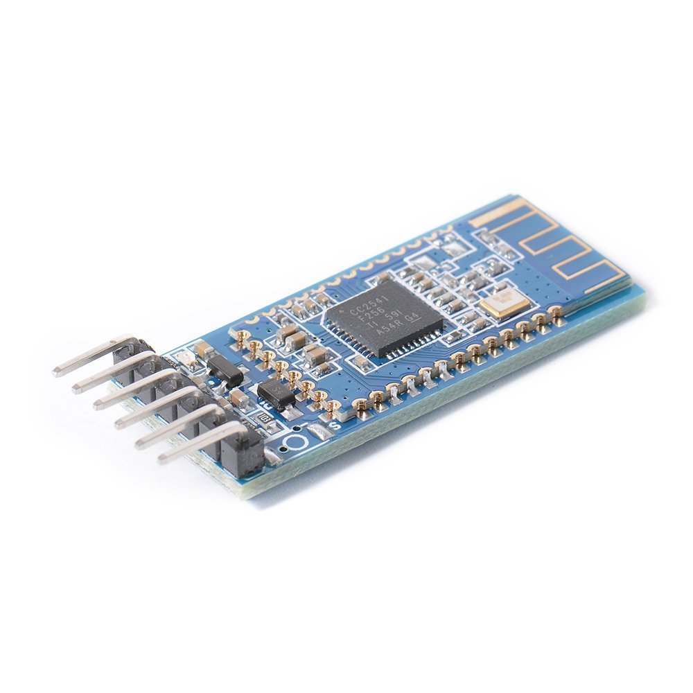
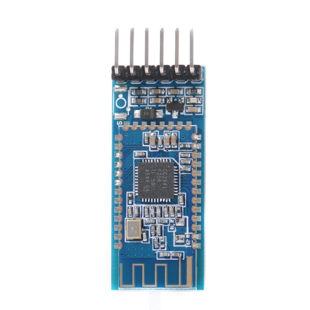
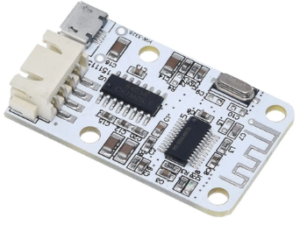
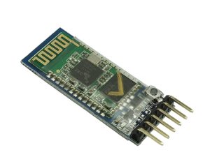
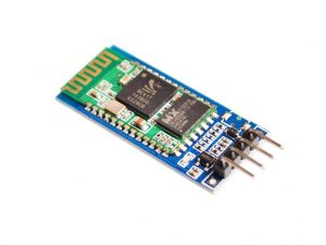
- CC41 BLE Bluetooth 4.0 UART Transceiver Serial Module, with low-power dissipation, uses the U.S. TI’s CC2541 chip configuration 256Kb space, and follows the Bluetooth specification V4.0 BLE.
- Supports AT commands; the user can modify the serial port baud rate, device name, password and other parameters according to the pair.
- The module supports UART interface, and supports Bluetooth SPP serial protocol.
- Connected with Iphone 4S and Android 4.3 above.
- The most complete, most convenient, and most stable Bluetooth data transmission, remote control,
- and data acquisition module.
- Master-slave in one, transparent transmission, replacing serial port.
- Remote control, Remote data acquisition, transparent transmission, MCU is unnecessary.
- Bluetooth protocol: Bluetooth Specification V4.0 BLE, receive no byte limit, Iphone 4s under open environment
- Operating frequency: 2.4GHz ISM band
- Modulation: GFSK (Gaussian Frequency Shift Keying)
- Sensitivity: ?-84dBm at 0.1% BER
- Transfer Rate: Asynchronous: 6 kbps Synchronous: 6 kbps
- Safety features: Authentication and encryption
- Support Services: Central & Peripheral UUID FFE0, FFE1
- Power consumption: automatic sleep mode, standby current 400uA ~ 1.5mA, transmission 8.5mA.
- The power can be adjusted through an AT Command (AT+POWER).
- Range: up to 100 meters in open space
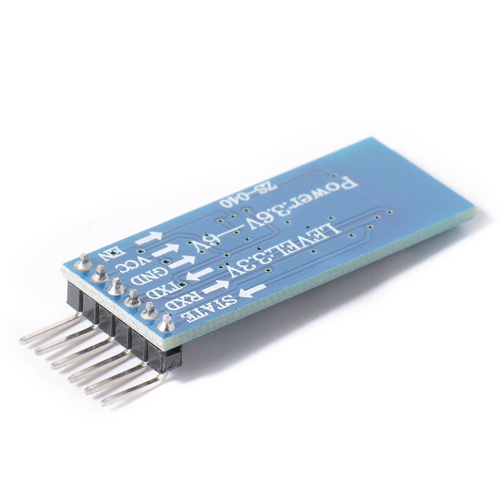
- Power supply: +3.3V DC 50mA
- Flash:256Kb
- Dimensions: 26.9mm x 13mm x 2.2 mm
- Bluetooth Certification: ROHS REACH
Applications:
- Industrial remote control, remote sensing, POS system, Bluetooth keyboard, mouse,joystick
- Automobile testing equipment
- Portable, battery-powered medical equipment
- Wireless LED display system
- Smart Home
How to get satrted with BT05 BLE Bluetooth 4.0 CC2540 CC2541 Serial Wireless Module
To see if the connections are correct we use the “AT” command. The “AT” command is used to confirm communication is working and all it does is return an “OK”. “AT” can also be used to break an active connection.
BT05 BLE Bluetooth 4.0 connection to arduino uno

then copy paste the following code, which is just a modification of Software Serial example included in arduino examples.
#include <SoftwareSerial.h>
SoftwareSerial mySerial(2, 3); // TX, RX
void setup() {
Serial.begin(9600);
Serial.println(“Enter AT commands:”);
mySerial.begin(9600);
}
void loop()
{
if (mySerial.available())
Serial.write(mySerial.read());
if (Serial.available())
mySerial.write(Serial.read());
}
Now as your bluetooth is connected to your PC upload the above code in the Arduino IDE (I’m using this one to control the Master bluetooth module). hence open your serial monitor with the correct baud rate (9600).
The HC-05 expects commands to include a carriage return and newline characters (rn). You can add these automatically in the serial monitor by selecting Both NL & CR at the bottom of the window.

Enter “AT” (no quotes) in the text box and click Send. If everything is working you should see “OK”

To check the modules name use AT+NAME?

To get the modules address, use AT+ADDR?

To get the modules Bluetooth characteristic, either use AT+CHAR?

To find the UUID use AT+UUID? This returns OK+Get:0xFFE0.

Common AT commands
Here is a list of the main AT commands. Remember that commands should be in uppercase and not include line ending characters (\r\n) unless you are using the above sketch in which case it does not matter if you include line end characters or not.
| AT | Test Command or Disconnect Command | If the module is not connected to a remote device it will reply: “OK” If the module has a connection then the connection will be closed. If the notification setting is active, the module will reply with “OK+LOST” |
| AT+NAME? | Query the name | Returns the name the module broadcasts such as HMsoft. |
| AT+NAMEnewname | Change the name of the module | Changes the name broadcast by the module. For example AT+NAMEmyBTmodule changes the name to myBTmodule. The maximum length for a new name is 12 characters. |
| AT+ADDR? | Queries the HM-10s mac address | Returns the address as a 12 digit hexidecimal number. For example, OK+ADDR:606405D138A3 |
| AT+VERS? AT+VERR? |
Queries the firmware version number | For example: HMSoft V540 |
| AT+RESET | Restarts the module. | Returns OK+RESET Will close an active connection while restarting. |
| AT+RENEW | Restores the default factory settings. | A quick and easy way to reset all settings. |
| AT+BAUD? | Query the baud rate used for UART serial communication. This is the speed a host device like an Arduino uses to talk to the BT module. It is not the the speed used to send wireless signals between different modules. | Returns the value 0-8, for example, OK+Get:0 0 – 9600 1 – 19200 2 – 38400 3 – 57600 4 – 115200 5 – 4800 6 – 2400 7 – 1200 8 – 230400 The default setting is 0 – 9600. Remember that both devices, the Arduino and the HM-10 need to use the same baud rate. Garbage characters are usually a sign of mismatched baud rates. |
| AT+BAUDx | Set the baud rate used for UART serial communication. | x is a value from 0 to 8. See the above for wwhat value represents which baud rate. Take care when using with an Arduino. The maximum baud rate the Arduino serial monitor allows is 115200. If you set the baud rate to 230400 with AT+BAUD8 you wont be able to talk to the module. |
| AT+NOTI | Set the notification status | If notifications are turned on, the HM-10 will reply to commands with a confirmation message or send out a message when certain events take place, like “OK” for the AT command and “OK+LOST” when a connection is broken.AT+NOTI0 – turn off notifications AT+NOTI1 – turn on notifications |
| AT+NOTI? | Query the notification status | Returns either 0 or 1: 0 – notifications are off 1 – notifications are on |
| AT+PASS? | Query the password used for pairing. | Replies with a 6 digit number like “OK+Get:123456” or whatever the current password is. |
| AT+PASS | Set a new password. | The password must be 6 characters long.. AT+PASS123456 sets the new password to 123456 |
| AT+ROLE? | Query the current Role; Master or Slave | AT+ROLE? returns either 0 or 1. 0 = Slave or Peripheral 1 = Master or Central. The default setting is 0 (Slave). |
| AT+ROLEx | Set the device role. x is 0 or 1. | To change to Slave/Peripheral mode use AT+ROLE0. This will return OK+Set:0 To change to Master/Central mode use AT+ROLE1. This will return OK+Set:1 AT+ROLEx mat require a reset before the changes take place. |
| AT+IMME? | Query the start mode | AT+IMME? returns either 0 or 1. 0 = Connect immediately (assuming a previous connection has been applied 1 = Wait for a connection command before connecting (AT+START, AT+CONN, AT+CONL The default setting is 0 (connect on start). |
| AT+IMMEx | Set the start up mode | AT+IMME0 sets auto connect on start* AT+IMME1 sets manual connection mode AT+IMMEx is often used together with AT+ROLEx AT+IMMEx mat require a reset before the changes take place. |
| AT+RESET | Restarts the module | |
| AT+RENEW | Resets the module to the factory settings |
BT-05 : Turning an LED on and off
We now try LED remote control. This is a very simply example, when a button switch is pressed a remote LED comes on. When the button switch is released the LED goes out.
On Arduino #1 we add a button switch to D2 and on Arduino #2 we add a LED to D4.
The switch on Arduino #1 is pulled down with a 10K resistor. This means pressing the button switch makes the Arduino pin go LOW to HIGH.
The LED on Arduino #2 is connected inline with a 220 ohm resistor (330 ohm is also OK).
The sketch on the master Arduino uses 3 AT commands to set up the Central HM-10 and start the connection. These are the same commands we used in the manual connection example above.
This is not really the best solution but it works and it keeps the example easy to understand. Of course, if the HM-10 is already in Central mode and in manual start mode the first 2 commands are not required. The delays allow time for the replies. You could, if you wished, check for the correct reply before moving to the next command. Change the address to suit the modules you are using.
If you are using an older firmware you will need to add a “AT+RESET” command after the “AT+ROLE1”.
You could do away with these commands by using the auto-connect mode.
After this, the sketch checks the status of the pin connected to the button switch and if it has changed sends out 1 of 2 commands.
- LOW to HIGH. The button switch has been pressed so we want to turn on the LED. This is done by sending a “1” to the remote module.
- HIGH to LOW. The button switch has been released so we want to turn off the LED. This is done by sending a “0” to the remote module.
Note that we are sending ascii “1” and ascii “0” not the value 1 and the value 0.
On the first Arduino we have BT-05 Bluetooth 4.0_Example_01_simple LED_Master
// HM-10_Example_01_simpleLED_Central
//
// Simple remote control using HM-10s: LED on. LED off
//
//
// Pins
// BT VCC to Arduino 5V out.
// BT GND to GND
// Arduino D8 (ASS RX) – BT TX no need voltage divider
// Arduino D9 (ASS TX) – BT RX through a voltage divider
//
#include <AltSoftSerial.h>
AltSoftSerial BTserial;
byte switchPin = 2;
boolean switch_State = LOW;
boolean oldswitch_State = LOW;
void setup()
{
Serial.begin(9600);
Serial.print(“Sketch: “); Serial.println(__FILE__);
Serial.print(“Uploaded: “); Serial.println(__DATE__);
Serial.println(” “);
BTserial.begin(9600);
Serial.println(“BTserial started at 9600″);
Serial.println(” “);
pinMode(switchPin, INPUT);
// connect to the remote Bluetooth module
BTserial.print(“AT+IMME1” );
delay(1000);
BTserial.print(“AT+ROLE1” );
delay(1000);
BTserial.print(“AT+CONA81B6AAE5221” );
delay(1000);
}
void loop()
{
// Very simple debouce.
boolean state1 = digitalRead(switchPin); delay(1);
boolean state2 = digitalRead(switchPin); delay(1);
boolean state3 = digitalRead(switchPin); delay(1);
if ((state1 == state2) && (state1==state3))
{
switch_State = state1;
if (switch_State != oldswitch_State)
{
if ( switch_State == HIGH) { BTserial.print(“1” ); Serial.println(“1”); }
else { BTserial.print(“0” ); Serial.println(“0”); }
oldswitch_State = switch_State;
}
}
}
On the second Arduino we have BT-05 Bluetooth 4.0_Example_01_simple LED_Slave.


