Description
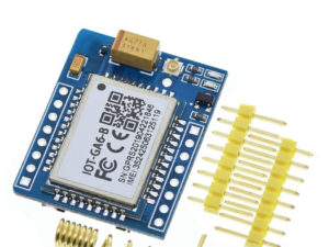
A9G GSM/GPRS/GPS module by Ai-thinker is an integrated IoT solution that supports dual band GSM/GPRS network and at the same time It has an embedded GPS module. If your project involves both GSM and GPS module then the A9G GSM GPS is a good choice.
The board features compact size and low current consumption. With power saving capabilities, the current consumption is as low as 3mA in sleep mode. It communicates with microcontroller via UART port supports AT commands.
The A9G by default comes with a bootloader or firmware and hence it can be controlled using AT commands through Arduino, ESP8266, and Raspberry Pi as well. It can be used to connect modules such as Arduino and Raspberry Pi to the internet and can be used in a wide range of IoT applications and is ideal for IoT applications for home automation, industrial wireless control, wearable electronics, wireless location sensing devices, wireless location system signals, and other IoT applications.
Features
- Module: Ai Thinker A9G
- Supports voice call and SMS message.
- Operating Voltage: 3.3V – 4.2V
- Quad Band Frequencies: 850/900/1800/1900 MHz
- Standby Current: < 2mA
- Support GPS, BDS (Beidou chinese sattelite positioning system)
- Supports GPRS data service, the maximum download data rate is 85.6 Kbps, upload data is 42.8 Kbps
- Supports digital audio and analog audio
Specifications
- Size: 19.2mm x 18.8mm x 3mm
- Working temperature: -30 ℃-80℃
- Working voltage: 3.5v – 4.2v (it’s best to power by 4v)
- Power voltage: >3.5v
- Low power consumption:
- Sensitivity:
- GPIO level: 2.8v
Connection
- Connect usb-ttl with 4 wires when debugging, VUSB-5V; GND-GND; AT_TX-RX; AT_RX-TX
- Or power supply by USB, then connect another three lines, GND-GND; AT_TX-RX; AT_RX-TX
- Or power by lithium battery, VBAT-(3.3v-4.2) V; GND-GND; AT_TX-RX; AT_RX-TX; (VBAT power supply, need to press power_key button for about 2s)
Power on
- A9G development board can be powered by USB or lithium battery.
- It does not require any operation when powered 1-2s.
- Please press the Rst_Key button to reset.
- The module enters AT command mode by default.
Structural details of the module are as mentioned below

Getting started with the A9G GPS GSM GPRS Development Board
In this guide, I will try to briefly explain the first steps to work with the A9G with GSM, GPS, GPRS modules. I will install the necessary software and try to control it using AT commands.
Hardware required
- USB to Serial CP2102 Converter
- A9G GPS GSM GPRS Development Board
- Jumper wires
Connecting the Hardware

1) Connect the GSM and GPS antennas to the A9G module.
2) Insert a SIM card in the SIM card slot and a Micro SD card in the SD card slot
3) Connect the Vcc and GND Pin of the module to the Vcc and GND of the USB to Serial Converter.
4) Connect the Rx Pin of the A9G to the Tx pin of the Converter and Tx Pin of A9G to the Rx pin of the converter and connect it to your PC.
5) Open AI Thinker Tool and select the correct COM port and baud rate(In this case it is 115200) and click open Serial button.
If all the components are present, download the program to control the module using AT commands: Download
At the first steps of learning a new device, you need to try all of its functionality. The module comes with firmware that allows you to accept AT commands and process them. We connect the module via a TTL converter

Steps for using GPS functions of the module:
1) In the command, section write command AT and click Send button. It must display OK on the monitor which shows that your module is connected successfully.
2) Now to enable GPS we need to send a command AT+GPS=1. This turns ON the GPS and as it turns ON the GPS LED starts blinking.
3) After this, we will send a command AT+GPSRD=5. This command will read the GPS data and send it to the monitor after every 5 seconds. The Data appearing on the Monitor would be in NMEA format which can be converted to get the GPS data details.
4) To stop this we need to send command AT+GPSRD=0 and it will stop sending GPS data and after that send the command AT+GPS=0 which will disable GPS as well.

Steps for using GPRS functions of the module:
1) To check the status of the GPRS we can use commands such as AT+CREG? if this command shows 1, 1 on the monitor it means that we are registered to the network. Similarly, we can use AT+CGATT command which shows 1 when we are connected to the network
2) To connect to the Internet using GPRS we need to send a command which is AT+CGDCONT=1, “IP”, “www”. where “IP” is the Internet Protocol and “www” is the Access Point Name which can be different in your case. As we send the command it should display OK which means that we are connected to GPRS.
3) Use AT+CIPSTATUS command to check whether IP is connected or not it should display “Initial”.
4) To send an HTTP request we need to type a command which is AT+HTTPGET=”anyserver link” this will send a get request to the server link which is mentioned after the “=” sign. As the command is sent, the monitor will display the data received and in that the bottom line is the response sent by the server.
Using GSM Functionality of A9G Module
The A9G module has GSM capabilities with the help of which it can be used to start a call, receive a call, and send an SMS as well when we dial the number whose SIM card is inserted within the A9G module a “RING” message will continuously appear on the monitor. The AT Commands which can be used for calling and sending SMS using the A9G are:-
Call Commands:
- ATA: Used to Answer an Incoming Call. On sending this command “+CIEV: “CALL”, 1 CONNECT”; the message is received.
- ATD: This Command is used to dial a number this command is sent as “AT+number to be dialed” and on sending this command we receive a message saying “ATD+number dialed OK +CIEV: “CALL”, 1 +CIEV: “SOUNDER”, 1 “;
- ATH: This command is used to disconnect a call. This command is sent as “ATH” and on sending this we receive a message “+CIEV: “CALL”, 0 OK”;
- AT+SNFS=0: This command used to enable any earphones/headphones connected to the module. This command enables them.
- AT+SNFS=1: This command is used to enable Loudspeaker selection.
- AT+CHUP: This command causes the mobile terminal to hang up the current call
SMS Commands:-
- AT+CMGF=1: This command is used to select the SMS message format. On sending his command we receive an OK. This is to read and write SMS messages as strings instead of hexadecimal characters.
- AT+CMGS: This command is used to send SMS to a given mobile number. The format for sending this command is “AT+CMGS=” mobile number”.On sending this command the monitor will show > You can now type the message text and send the message using the – key combination: TEST After some seconds the modem will respond with the message ID of the message, indicating that the message was sent correctly: “+CMGS: 62”. The message will arrive on the mobile phone shortly.
- AT+CMGL: This command is used to read SMS messages from preferred storage.
So this was it from the tutorial as you can see that the A9G module is capable of doing many things such as GPS functions, GPRS functions such as calling, sending SMS, connecting to the internet, etc which makes it very useful in IoT related applications where we need to use GPS location data as well. As it can be driven using AT commands it is very easy to operate this module and can prove to be a good and compact tool for your projects.


