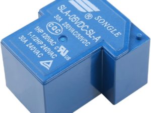
Description
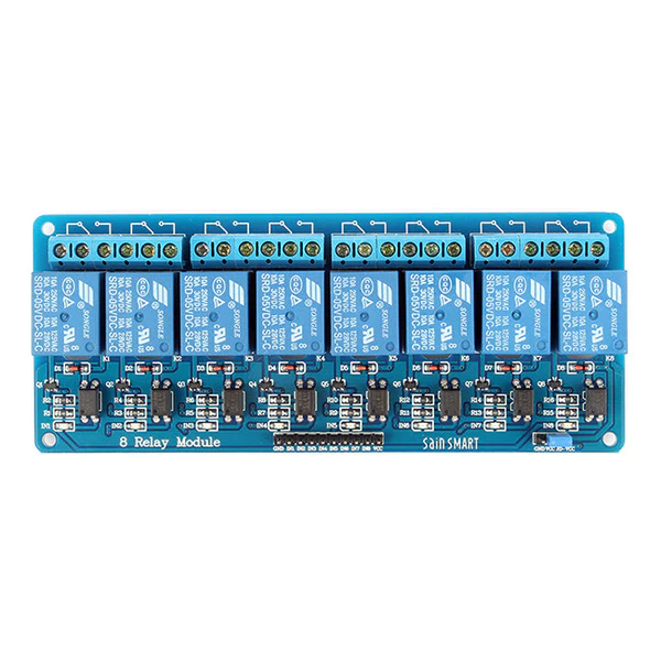
It is a 5V 8 Channel Relay Module. The relay normally open interface maximum load: AC 250V/10A, DC 30V/10A. It has a trigger current of 5mA, and module working voltage of DC 5V. Each channel of the module can be triggered by a jumper to set a high level or a low level.
- Supply voltage – 3.75V to 6V
- Trigger current – 5mA
- Current when relay is active – ~70mA (single), ~600mA (all eight)
- Relay maximum contact voltage – 250VAC, 30VDC
- Relay maximum current – 10A
Features:
- A fixed bolt holes for easy installation.
- It has a relay status indicator led Power LED(Green), 8 relay status indicator LED(Red)
- Relay control interface by single-chip IO.
- Low-level suction close, high-level release.
- Easy to use, simple 3 line structure.
Getting started with the 8 Channel 5V Relay Module
Arduino Relay Shield employs high quality relay with eight channels input and eight channels output. It can be connected to 250V/10A AC element or 24V/10A DC element to the maximum, therefore, it can be used to control lights, motors. The modularized design makes it easy to connect to Arduino expansion board. The output state of the relay is shown by a luminous diode for the convenience of actual application.
Hardware required
- Arduino Uno
- Jumper wires
- Led x3
- 8 Channel 5v Relay module
Connecting the Hardware

Upload the code


