Description
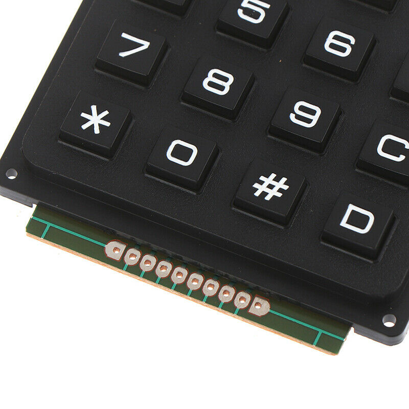
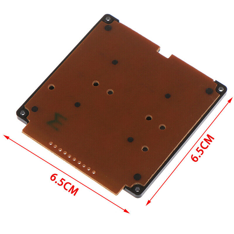
This high quality 4×4 Keypad Matrix lets you quickly add controls to your electronics projects. It offers 0-9 numerals, A-D letters, and standard star(*) and hash(#) symbols.
Features:
- 100% brand new and high quality.
- 16 Button Matrix 0-9 # * A-D
- Excellent price-performance ratio Easy communication with any microcontroller
Getting started with the 16 Key Membrane Switch Keypad Keyboard 4x4x4 Matrix Array
We are going to show how to connect a 4 x 4 Membrane Keypad to an Arduino.
Step1: Hardware required
Step2: Connecting the Hardware
The connections are pretty straightforward. Start by connecting pin 1 of keypad to digital pin 9 on Arduino. Now keep on connecting the pins leftwards like 2 with 8, 3 with 7 etc.
Keypad Arduino UNO
PIN 1 Connected to Pin 9
PIN2 Connected to Pin 8
PIN3 Connected to Pin 7
PIN4 Connected to Pin 6
PIN5 Connected to Pin 5
PIN6 Connected to Pin 4
PIN7 Connected to Pin 3
PIN8 Connected to Pin 2
Step3: Upload the Code
#include “Adafruit_Keypad.h”
const byte ROWS = 4; // rows
const byte COLS = 4; // columns
//define the symbols on the buttons of the keypads
char keys[ROWS][COLS] = {
{‘1′,’2′,’3′,’A’},
{‘4′,’5′,’6′,’B’},
{‘7′,’8′,’9′,’C’},
{‘*’,’0′,’#’,’D’}
};
byte rowPins[ROWS] = {5, 4, 3, 2}; //connect to the row pinouts of the keypad
byte colPins[COLS] = {9, 8, 7, 6}; //connect to the column pinouts of the keypad
//initialize an instance of class NewKeypad
Adafruit_Keypad customKeypad = Adafruit_Keypad( makeKeymap(keys), rowPins, colPins, ROWS, COLS);
void setup() {
Serial.begin(9600);
customKeypad.begin();
}
void loop() {
// put your main code here, to run repeatedly:
customKeypad.tick();
while(customKeypad.available()){
keypadEvent e = customKeypad.read();
Serial.print((char)e.bit.KEY);
if(e.bit.EVENT == KEY_JUST_PRESSED) Serial.println(” pressed”);
else if(e.bit.EVENT == KEY_JUST_RELEASED) Serial.println(” released”);
}
delay(10);
}
Step4: Testing the circuit
Here’s how the output looks like in the serial monitor.


