


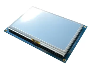
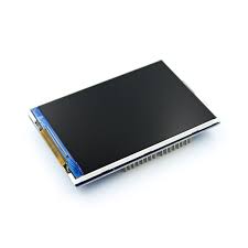
Description
- 3.5-inch color screen, supports 65K color display, rich display colors
- 480X320 HD resolution, optional touch function
- Using SPI serial bus, only a few IOs are needed to light up the display
- With SD card slot for convenient expansion experiments
- Provide rich sample programs
- Military-grade process standards, long-term stable work
- Provide underlying driver technical support
Product Description
| Name | Parameter |
| size | 3.5(inch) |
| TYPE | TFT |
| Driver chip | ILI9488-9486-9481 |
| Resolution | 480*320 (PIXEL) |
| Module interface | 4-WIRE SPI interface |
| Effective display area (AA area) | 48.96×73.44(mm) |
| Module PCB backplane dimensions | 55.1×96.18(mm) |
| Touch type | Optional resistance touch |
| VCC IO port voltage | 3.3v~5v |
| Power consumption | About 90Ma |
| Logic IO port voltage | 3.3v(TTL) |
3.5″ TFT Touch Screen with DOIT ESP32 DEVKIT V1
Hardware Required:
1. Pin Connection
| Serial number | Label | Pin description |  |
ESP32 |
|---|---|---|---|---|
| 1 | VCC (VDD) | Power input (3.3v-5v) | |
3.3V |
| 2 | GND | I power ground | |
GND |
| 3 | CS | LCD chip select | |
GPIO15 |
| 4 | RESET (RST) | LCD reset | |
GPIO4 |
| 5 | DC | LCD bus command/data selection | |
GPIO2 |
| 6 | SDI (MOSI) | LCD SPI display bus data input | |
GPIO23 |
| 7 | SCK | I LCD SPI display bus clock signal | |
GPIO18 |
| 8 | LED (BL) | LCD backlight control (high level lights up) | |
3.3V |
| 9 | SDO (MISO) | LCD SPI display bus data input and output | |
GPIO19 |
| 10 | T CLK | Touch panel SPI bus clock signal | |
GPIO26 |
| 11 | T CS | Touch panel SPI bus chip select | |
GPIO25 |
| 12 | T DIN | Touch panel SPI bus data input | |
GPIO33 |
| 13 | T DO | Touch panel SPI bus output | |
GPIO32 |
| 14 | IRQ (PEN) | Touch panel interrupt IRQ signal | |
GPIO35 |
2. Library Used
3. Changes Made in User_Setup.h file of TFT_eSPI library
After adding TFT_eSPI library to your IDE, you will need to make some modifications to User_Setup.h file to make everything work. In this repository, there is a copy of User_Setup.h with modifications. The following are some modification made to the file:
- Defining driver [one to be defined the other ones must be commented out] (line 45-64)
- Defining the pins that are used to interface with the display here (line 112)
- Comment out ESP8266 NodeMCU pins and uncomment ESP32 pins
- Define the ESP32 SPI port to use (line 374)
- As we are using Virtual SPI (VSPI) port, we need to uncomment this line
4. Calibration
With the Touch_Calibration sketch, the min/max values (TS_MINX, TS_MAXX, TS_MINY, TS_MAXY) will be available in the serial monitor for direct use in your touchscreen mapping logic.
In you sketch you will need to replace these values with the one you have got:
Note: This is tested on ILI9488_DRIVER. If you have different type, update the User_Setup.h file
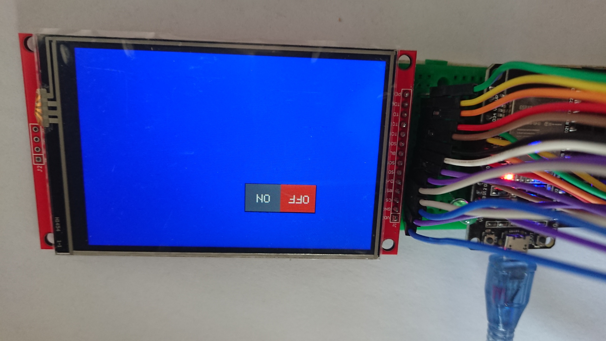
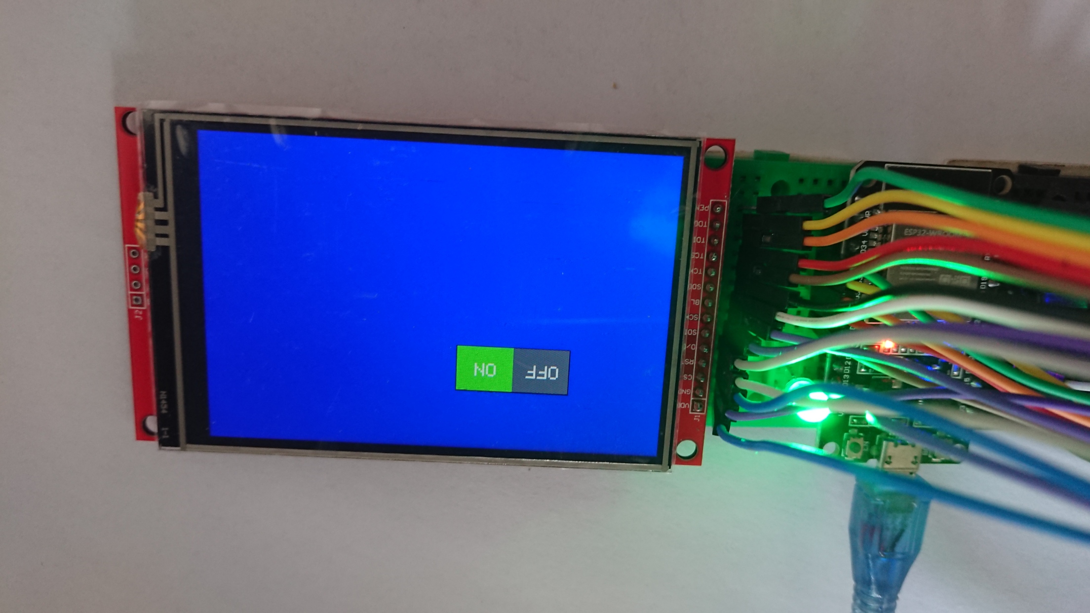
5. On/Off Button Example
The On/Off Button Example is designed to toggle an LED connected to pin 12. However, you might encounter a “flipping” issue, where the touch input does not align with the location of the desired effect on the screen. This issue arises because the raw touchscreen coordinates do not correspond directly to the screen’s orientation or dimensions. To resolve this, calibration is required to map the raw touch coordinates accurately to the display area, accounting for any flipping or mismatches.
Here are some key areas you may change in your codes
- Screen dimensions
- Screen rotation
- Mapping raw touch coordinates to screen coordinates
Upload the codes into your board and you will be getting the same screen as shown below:
Reviews
There are no reviews yet.