Description
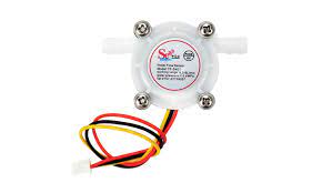
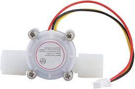
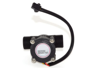
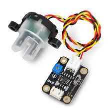
Water flow sensor is mainly composed of a plastic body, the flow of the rotor assembly and the Hall sensor. Which is mounted in the water heater inlet end for detecting water flow, the water flow through the water when the rotor assembly, and the speed of rotation of the rotor with a magnetic flow change, the Hall sensor output a corresponding pulse signal, feedback to the controller, the control is to determine the size of the water flow regulation.
Wiring:
Red – In – Connect positive
Yellow – Out – Signal output
Black – GND – Connect negative
Size
 Technical Parameters:
Working range: 0.3-6L/min
Water pressure: ≤0.8MPa
Minimum rated working voltage: DC4.5 5V-24V
Maximum working current: 15 mA(DC 5V)
Working voltage range: DC 5~18 V
Load capacity: ≤10 mA(DC 5V)
Operating temperature range: ≤80℃
Operating humidity range: 35%~90%RH (no frost)
Storage temperature: -25~+ 80℃
Storage humidity: 25%~95%RH
Size (L x W x H): Approx. 5.8 x 3.4 x 2.7cm / 2.28 x 1.34 x 1.06 inch
Output interface diameter: Approx. outer 7mm, inner 3mm
Application:
- water heater thermostat
- water purifier
- boiler
- water dispensers
- coffee machines
- smart card equipment
- the boiler and so on
Getting started with the Water Flow Sensor (Flow-meter)
In this tutorial you will learn how to use one water flow sensor with an Arduino board.
The water flow sensor consists of a plastic valve body, a water rotor and a hall-effect sensor. When the water flows through the rotor, rotor rolls and the speed of it changes with a different rate of flow. The hall-effect sensor outputs the corresponding pulse signal. This type of sensor can be found on different diameters, water pressure (MPa) and flow rate (L/m) ranges. Make sure to select one that will cover your needs. The sensor that I have it has 0-0.8MPa water pressure and ~3-6L/min flow rate range. In this tutorial we will use the serial monitor for printing the water flow rate in liters per hour and the total of liters flowed since starting.
Hardware required
Connecting the Hardware
Connect the Water flow sensor to the Arduino UNO as shown below

Upload The Code And Test
Measure the liquid/water flow rate using this code.
Connect Vcc and Gnd of sensor to arduino, and the
signal line to arduino digital pin 2.
NOTE: IF you get stray ‘223’ errors ,stray ‘\226’ in program The problem is with your ” / = ( and ” ) – * > characters. Replace them with ordinary quotes ” / = ” () – * > and you should be fine.
Now that all of the code has been written it can be uploaded to your Arduino! Click “Upload” button in the top left corner of the Arduino IDE and it should upload without any issues.
Next, click the “Serial Monitor” button in the top right corner (it looks like a magnifying glass). After a few seconds you should start to see a stream of data appear in the window – that is your flow in Liters/Minute.


