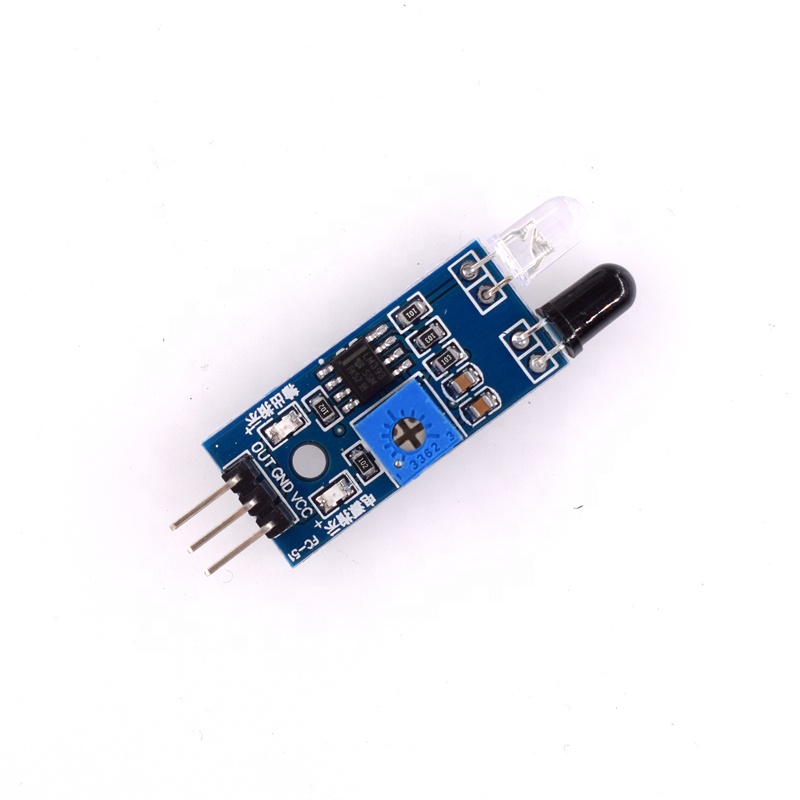
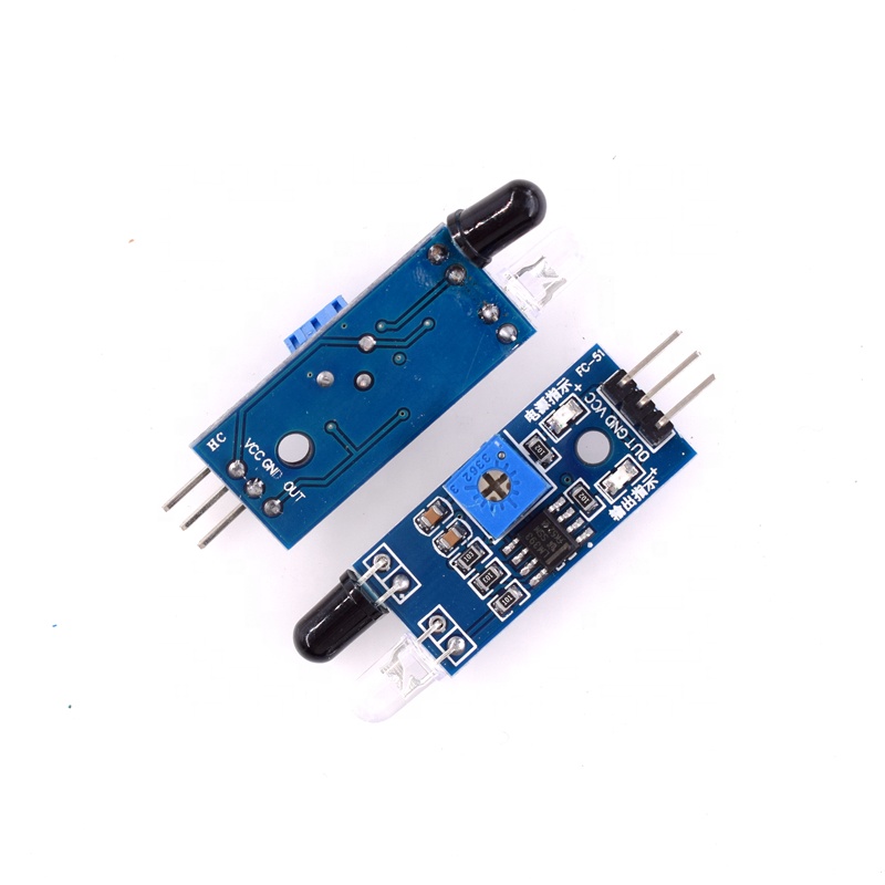
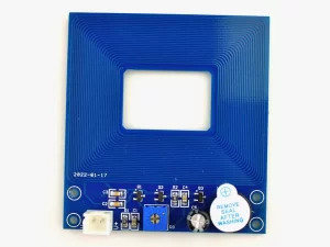
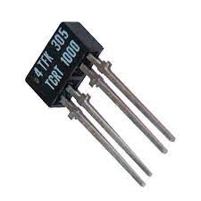
Description
Transmitter launch a certain frequency infrared, when meet obstacle in the detection direction, the infrared receiver is reflected back by the receiver tube, after processing through the comparator circuit, the green indicator light will illuminate while the signal output interface output digital signal (a low-level signal) can be adjusted via potentiometer.
Specifications:
- The module detects the distance 2 ~ 30cm, detection angle 35 °,
- The sensor module output port OUT can be directly connected with the microcontroller
- IO port can also be driven directly to a 5V relay
- It uses a stable comparator which is LM393
- The module is supplied with 3-5V DC power
- OUT : digital output interfaces (0 and 1);
Getting started with the Obstacle Infrared Sensor module
The device consists of an Infrared Transmitter, an Infrared Detector, and support circuitry. It only requires three connections. When it detects an obstacle within range it will send an output low.
Hardware required
- Obstacle Infrared Sensor module
- Arduino UNO
- Jumper wires
Obstacle Infrared Sensor module Pin Outs

Connecting the Hardware
Use the picture below. It only requires three wires.

Copy, Paste and Upload the Sample Sketch
Test the Tutorial Sketch
Move your hand towards the Obstacle Infrared Sensor module . Open your serial monitor and vary the distance of your hand while viewing the serial monitor. The output should look like the picture below:


