Description
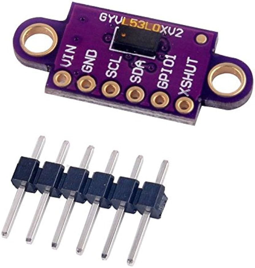
The VL53L0X from ST Microelectronics is a time-of-flight ranging system integrated into a compact module. The VL53L0 uses ST’s FlightSense technology to precisely measure how long it takes for emitted pulses of infrared laser light to reach the nearest object and be reflected back to a detector, so it can be considered a tiny, self-contained lidar system. This time-of-flight (TOF) measurement enables it to accurately determine the absolute distance to a target without the object’s reflectance greatly influencing the measurement.
Features:
- so it can be considered a tiny, self-contained lidar system.
- VIN This is the main 2.6 V to 5.5 V power supply connection.
- The VL53L0X from ST Microelectronics is a time-of-flight ranging system integrated into a compact module.
- This board is a carrier for the VL53L0X, so we recommend careful reading of the VL53L0X datasheet (1MB pdf) before using this product.
Getting started with VL53L0X
in this tutorial we are going to see how to interface the VL53L0X sensor with arduino. The VL53L0X is a I2C sensor. That means it uses the two I2C data/clock wires available on most microcontrollers, and can share those pins with other sensors as long as they don’t have an address collision.The VL53L0X is a Time of Flight distance sensor like no other you’ve used! The sensor contains a very tiny invisible laser source, and a matching sensor. let’s start our tutorial
Step1: Hardware required
Step2: Connecting the Hardware
- Connect Vin to the power supply, 3-5V is fine. Use the same voltage that the microcontroller logic is based off of. For most Arduinos, that is 5V
- Connect GND to common power/data ground
- Connect the SCL pin to the I2C clock SCL pin on your Arduino. On an UNO & ‘328 based Arduino, this is also known as A5, on a Mega it is also known as digital 21 and on a Leonardo/Micro, digital 3
- Connect the SDA pin to the I2C data SDA pin on your Arduino. On an UNO & ‘328 based Arduino, this is also known as A4, on a Mega it is also known as digital 20 and on a Leonardo/Micro, digital 2
As shown below

Step3: Upload the sample sketch and test the circuit
firstly you need to have a library to make things easier, you can download the library here , after downloading the library install it by extracting the zipped file in arduino libraries folder.after reopen your arduino IDE go to file>examples>adafruit_VL53L0x>vl53l0x. as shown below

after upload the sketch and try to move the obstacle up and down from the sensor you will see something like that shown below. but if there is big distance (above 1.2 meters) the sensor will be out of range,make sure the baud rate is 115200 you can change it by opening the serial monitor in the down light corner


