Description
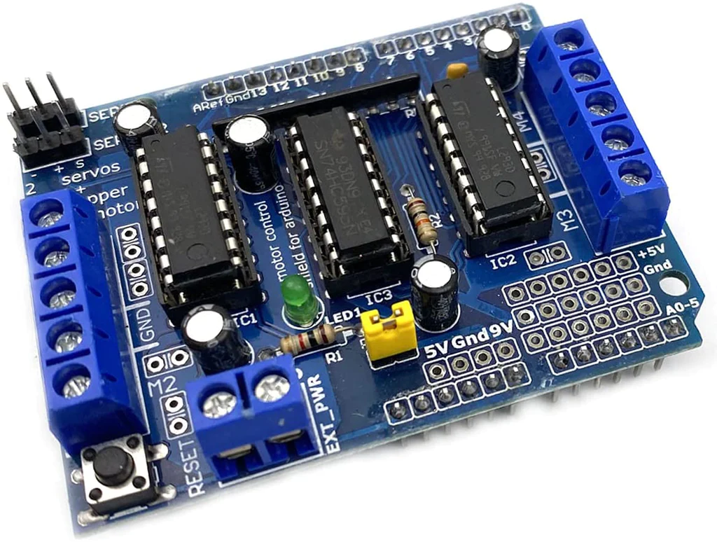
L293D is a monolithic integrated, high voltage, high current, 4-channel driver.Basically this means using this chip you can use DC motors and power supplies of up to 36 Volts, thats some pretty big motors and the chip can supply a maximum current of 600mA per channel, the L293D chip is also what’s known as a type of H-Bridge.
Features
- 2 interface for 5V Servo connected to For Ardui-no’s high-resolution dedicated timer – no jitter!
- Can drive 4 DC motors or 2 stepper motors or 2 Servo
- Up to 4 bi-directional DC motors with individual 8-bit speed selection
- Up to 2 stepper motors (unipolar or bipolar) with single coil, double coil or interleaved stepping.
- 4 H-Bridges: per bridge provides 0.6A (1.2A peak current) with thermal protection, can run motors on 4.5V to 36V DC
- Pull down resistors keep motors disabled during power-up
- reset button
- 2 external terminal power interface, for seperate logic/motor supplies
- Tested compatible for Ardui-no Mega, Diecimila & Duemilanove
Getting started with the Motor Drive Shield Expansion Board L293D
If you are planning on assembling your new robot, you will eventually want to learn about controlling variety of motors like DC motors, Stepper motors & servos. One of the easiest and inexpensive way to do that is to interface L293D Motor Driver Shield with Arduino.
Step1: Hardware required
- Arduino UNO
- DC motor/Servo motor/Stepper motor
- Jumper wires
Power Supply

There exists three scenarios when it comes to supplying power for the motors through shield.
- Single DC power supply for both Arduino and motors:
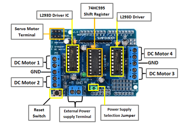
If you would like to have a single DC power supply for both Arduino and motors, simply plug it into the DC jack on the Arduino or the 2-pin EXT_PWR block on the shield. Place the power jumper on the motor shield.
You can employ this method only when motor supply voltage is less than 12V. - (Recommended) Arduino powered through USB and motors through a DC power supply:
If you would like to have the Arduino powered off of USB and the motors powered off of a DC power supply, plug in the USB cable. Then connect the motor supply to the EXT_PWR block on the shield. Do not place the jumper on the shield. - Two separate DC power supplies for the Arduino and motors:
If you would like to have 2 separate DC power supplies for the Arduino and motors. Plug in the supply for the Arduino into the DC jack, and connect the motor supply to the EXT_PWR block. Make sure the jumper is removed from the motor shield.
Output Terminals

The output channels of both the L293D chips are broken out to the edge of the shield with two 5-pin screw terminals viz. M1, M2, M3 & M4. You can connect four DC motors having voltages between 4.5 to 25V to these terminals.
Each channel on the module can deliver up to 600mA to the DC motor. However, the amount of current supplied to the motor depends on system’s power supply.
You can also connect two stepper motors to output terminals. One stepper motor to motor port M1-M2 and other to M3-M4.
The GND terminal is also provided if you happen to have a unipolar stepper motor. You can connect the center taps of both stepper motors to this terminal.
The shield brings out the 16bit PWM output lines to two 3-pin headers to which you can connect two servo motors.
Installing AFMotor Library
In order to communicate with the shield, we need to install AFMotor.h library so that we can issue simple commands to control DC, stepper & servo motors.
To install the library navigate to the Sketch > Include Library > Manage Libraries… Wait for Library Manager to download libraries index and update list of installed libraries.

Filter your search by typing ‘motor shield’. There should be a couple entries. Look for Adafruit Motor Shield library(V1 Firmware) by Adafruit. Click on that entry, and then select Install.

Driving DC Motors with L293D Shield
Now that we know everything about the shield, we can begin hooking it up to our Arduino!
Start by plugging the shield on the top of the Arduino.
Next, connect power supply to the motors. Although you can connect DC motors having voltages between 4.5 to 25V to the shield, in our experiment we are using DC Motors that are rated for 9V. So, we will connect external 9V power supply to the EXT_PWR terminal.
Now, connect the motor to either M1, M2, M3 or M4 motor terminals. In our experiment we are connecting it to M4.

The following sketch will give you complete understanding on how to control speed and spinning direction of a DC motor with L293D motor driver shield and can serve as the basis for more practical experiments and projects.
CODE
#include <AFMotor.h>

AF_DCMotor motor(4);

void setup()
{
//Set initial speed of the motor & stop
motor.setSpeed(200);
motor.run(RELEASE);
}

void loop()
{
uint8_t i;

// Turn on motor
motor.run(FORWARD);

// Accelerate from zero to maximum speed
for (i=0; i<255; i++)
{
motor.setSpeed(i);
delay(10);
}

// Decelerate from maximum speed to zero
for (i=255; i!=0; i--)
{
motor.setSpeed(i);
delay(10);
}

// Now change motor direction
motor.run(BACKWARD);

// Accelerate from zero to maximum speed
for (i=0; i<255; i++)
{
motor.setSpeed(i);
delay(10);
}

// Decelerate from maximum speed to zero
for (i=255; i!=0; i--)
{
motor.setSpeed(i);
delay(10);
}

// Now turn off motor
motor.run(RELEASE);
delay(1000);
}
Driving Stepper Motors with L293D Shield
Let’s connect stepper motor to the L293D shield. Start by plugging the shield on the top of the Arduino.
If you are using 28BYJ-48 unipolar stepper, those motors are rated at 5V and offer 48 steps per revolution. So, connect external 5V power supply to the EXT_PWR terminal.
Remember to remove the PWR jumper.
Now, connect the motor to either M1-M2(port#1) or M3-M4(port#2) stepper motor terminals. In our experiment we are connecting it to M3-M4.

For NEMA 17 bipolar stepper
If you are using NEMA 17 bipolar stepper, those motors are rated at 12V and offer 200 steps per revolution. So, connect external 12V power supply to the EXT_PWR terminal.
Remember to remove the PWR jumper.
Now, connect the motor to either M1-M2(port#1) or M3-M4(port#2) stepper motor terminals. In our experiment we are connecting it to M3-M4.

CODE
#include <AFMotor.h>

// Number of steps per output rotation
// Change this as per your motor's specification
const int stepsPerRevolution = 48;

// connect motor to port #2 (M3 and M4)
AF_Stepper motor(stepsPerRevolution, 2);

void setup() {
Serial.begin(9600);
Serial.println("Stepper test!");

motor.setSpeed(10); // 10 rpm
}

void loop() {
Serial.println("Single coil steps");
motor.step(100, FORWARD, SINGLE);
motor.step(100, BACKWARD, SINGLE);

Serial.println("Double coil steps");
motor.step(100, FORWARD, DOUBLE);
motor.step(100, BACKWARD, DOUBLE);

Serial.println("Interleave coil steps");
motor.step(100, FORWARD, INTERLEAVE);
motor.step(100, BACKWARD, INTERLEAVE);

Serial.println("Micrsostep steps");
motor.step(100, FORWARD, MICROSTEP);
motor.step(100, BACKWARD, MICROSTEP);
}
Driving Servo Motors with L293D Shield
Driving the servos with L293D shield is as easy as pie.
The motor shield actually breaks out Arduino’s 16bit PWM output pins #9 & #10 to the edge of the shield with two 3-pin headers.
Power for the Servos comes from the Arduino’s on-board 5V regulator, so you don’t have to connect anything to the EXT_PWR terminal.

As we are using the onboard PWM pins, the sketch uses IDE’s built in Servo library.
CODE
#include <Servo.h>

Servo myservo; // create servo object to control a servo
int pos = 0; // variable to store the servo position

void setup()
{
// attaches the servo on pin 10 to the servo object
myservo.attach(10);
}

void loop()
{
// sweeps from 0 degrees to 180 degrees
for(pos = 0; pos <= 180; pos += 1)
{
myservo.write(pos);
delay(15);
}
// sweeps from 180 degrees to 0 degrees
for(pos = 180; pos>=0; pos-=1)
{
myservo.write(pos);
delay(15);
}
}

