Description
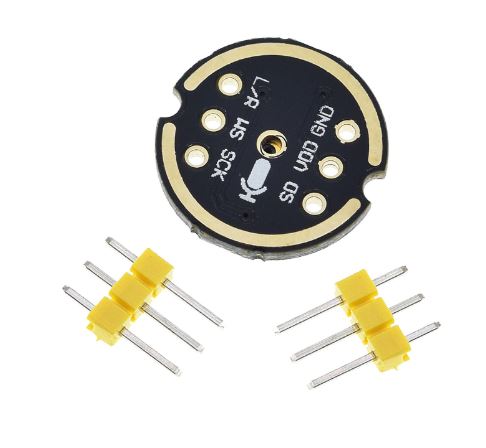
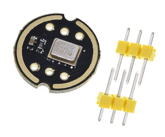
The INMP441 is a high-performance, low power, digital-output, omnidirectional MEMS microphone with a bottom port. The INMP441 is available in a thin 4.72 x 3.76 x 1 mm surface mount package. It is reflow- solder compatible with no sensitivity degradation. The INMP441 is halide free. The INMP441 has a high signal-to-noise ratio and is an excellent choice for near field applications. The INMP441 has a flat wideband frequency response that results in high definition of natural sound.
Features:
1. Digital I2S interface with high precision 24-bit data
2. High signal to noise ratio is 61 dBA
3. High sensitivity – 26 dBFS
4. Stable frequency response from 60 Hz to 15 kHz
5. Low power consumption: low current consumption 1.4 mA
6. High PSR: -75 dBFS
Interface definition:
- SCK: Serial data clock for I2S interface
- WS: Serial data word selection for I2S interface
- L/R: Left/Right channel selection.
When set to low, the microphone outputs a signal on the left channel of the I2S frame.
When set to high level, the microphone outputs signals on the right channel - SD: Serial data output of the I2S interface.
- VCC: Input power, 1.8V to 3.3V.
- GND: power ground
This product provides tutorials for using ESP32 modules with I2S functionality
Connect to ESP32:
- INMP441 >> ESP32
- SCK >> GPIO14
- SD >> GPIO32
- WS >> GPIO15
- L/R >> GND
- GND >> GND
- VDD >> VDD3.3
What is the difference between an omnidirectional microphone and a unidirectional microphone:
First of all, I understand that the sound divergence is all-round. One person speaks and diverge in the air.
As for how far it can pass, it depends on many factors.
1.directional microphone, the general pickup radius is very small, 30 cm is a big one, single use, put it on the mouth, the sound quality is very good, because it is not picked up again.
The shape is generally goose neck wheat, a rod, a curved rod, to your mouth, directivity, just listen to your voice.
With a single-point microphone, the sensitivity is limited to a certain range. Sensitivity is too hig
INMP441 Microphone Module Hookup
Here is how we will be hooking up our microphone module and ESP32.
Hardware requirements
- INMP441 Microphone Module
- ESP32 Development Board
- Connecting wires
- Mini Micro USB Cable for ESP32
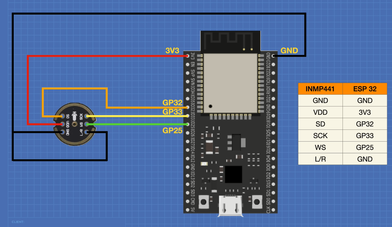
Note that your ESP32 may have a different pinout from the one illustrated here, use the GPIO numbers instead of physical pins to connect your module.
INMP441 Microphone Module Code
In our first experiment, we will be using the I2S Library that is installed in your Arduino IDE when you install the ESP32 Boards Manager files. Here is what the code looks like:
Testing the Microphone
Hook everything up, load the sketch and open the Serial Plotter.
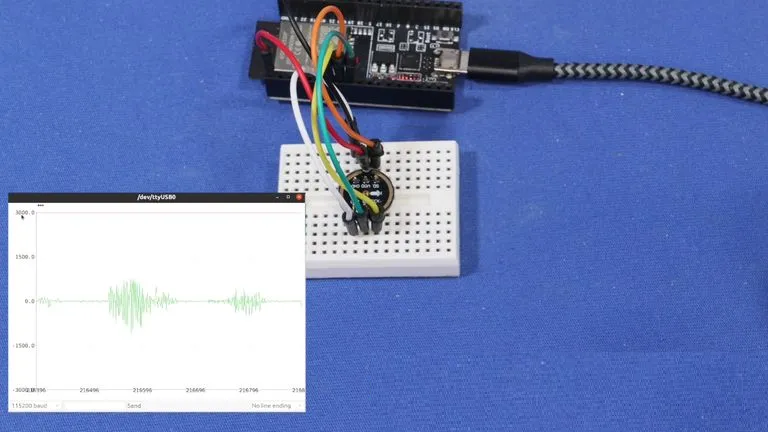
You should see a representation of the sound that the microphone is getting. You can adjust the sensitivity by altering the rangelimit variable in the Loop.


