Description
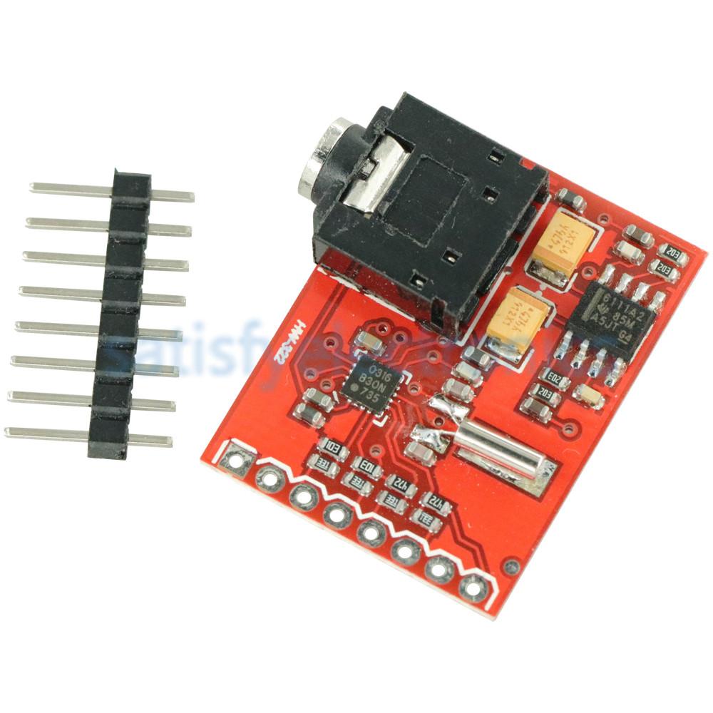
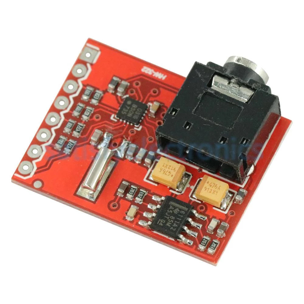
This is a breakout board for the Silicon Laboratories Si4703 FM tuner chip. Beyond being a simple FM radio, the Si4703 is also capable of detecting and processing both Radio Data Service (RDS) and Radio Broadcast Data Service (RBDS) information. The Si4703 even does a very good job of filtering and carrier detection. It also enables data such as the station ID and song name to be displayed to the user.
Using this board we are able to pick up multiple stations just as well as with a standard FM radio. The board breaks out all major pins and makes it easy to incorporate this great chip into your next radio project. Also, by plugging headphones into the 3.5mm audio jack, you effectively use the cable in your headphones as an antenna! Therefore, this board does not require an external antenna if using headphones or a 3.5mm audio cable longer than 3 feet.
Features
- worldwide FM band support
- digital low-IF receiver
- automatic frequency control (AFC)
- automatic gain control (AGC)
- volume control
- RDS/RBDS support
- Arduino® library available
- 150 mW amplifier stereo amplifier
- level shifters 5 V -3.3V on board
Specifications
- interface: I2C
- power / logic level: 3.3 – 5 V
- sensitivity: 1.7 µ emf
- max. output power: 150 mW (8 Ohm)
- default gain: 18 dB (8 x) (adjustable)
- dimensions: 29 x 22 mm
Getting Started
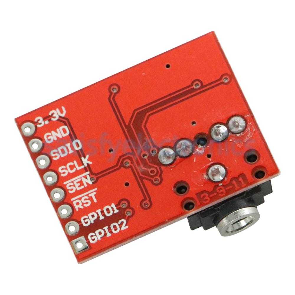
The Si4703 Breakout Board breaks out multiple pins from the IC. For the power bus, the 3.3V and GND pins are broken out. Keep in mind that while the IC is tolerant up to 5V, the communication pins are only 3.3V tolerant, and therefore should only be used in 3.3V systems.
For communication, the breakout board provides access to SDIO and SCLK for I2C communication. The RST pin is also broken out for ease of resetting the module.
SEN is also broken out, and enables the user to change the mode of functionality of the IC. SEN is pulled high on the breakout board to enable I2C communication as mentioned previously. However, by changing the state of SEN along with SDIO, you can change the mode of functionality between a 3-wire interface and 2-wire interface.
Finally, the last two pins broken out are the GPIO1 and GPIO2 pins. These can be used as general input/output pins, but also can be used for things like the RDS ready, seeking or tuning functions.
The board does not have a built-in antenna on it. However, by using headphones or a 3 foot-long 3.5mm audio cable, the wires will function as an antenna and will therefore negate the need for an external antenna on the board. If you are not planning on using either of these, you will need to modify the board to add in an antenna.
Connecting to Arduino
What you will need:
- Arduino uno
- Breadboard (or breadboard shield)
- Si4703 FM Board
- Headphones
Pin Connections
The connections are pretty easy, see the above image with the breadboard circuit schematic.
- 3.3V pin to Arduino uno 3.3V
- GND pin to Arduino uno GND
- SDIO pin to Arduino uno pin A4
- SCLK pin to Arduino uno pin A5
- RST pin to Arduino uno pin 2
Getting a Library
There are different library for this Si4703 module but both just do the same job. In this tutorial, we are going to get our library from Arduino Manage Libraries… and search for Si4703.
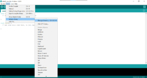
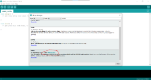
Now, Library is ready now. We need to get the example code that comes together with that Library.
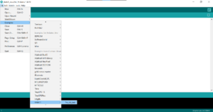
Before uploading codes, make sure connection are done well, right port is selected and right board is also selected. Then, you can change the FM channels to your local country channels. Note that while writing a channel, no dot is needed. For example, if we would like to switch to Radio Rwanda 100.7 FM, we are to write 1007 ignoring the dot. After that, upload your codes to your arduino.
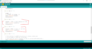
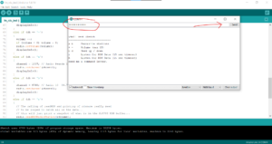
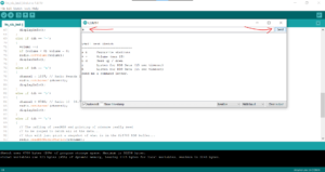
After uploading your codes, you can increase the volume by typing ‘+++++++++’ in your Serial monitor. Make sure the baud rate matches. By typing ‘a’, it should switch to you favorite channel setted in your code. If it doesn’t work, recheck for the connection but don’t try to reverse any pin. Some times, old Arduino Boards fail to run this FM module.
Now, you are good. It’s now your time for push-ups!
